The world as we know it is becoming more and more unstable with every passing day. Global warming, climate change, anticipated energy crisis, & the disrupted entropy, all these glaring issues originate from our primitive behavior of fossil fuel consumption.

A fuel cell generates power with minimal waste by harnessing the chemical energy of hydrogen or another fuel. When hydrogen is used as a fuel, electricity, water, and heat are the only results. When it comes to possible applications, fuel cells are unmatched. They can run on a wide variety of fuels and bioenergy, and they can drive systems as big as a primary power plant or as tiny as a laptop computer.
The Concept Dates Way Back
Hydrogen fuel cells were initially mentioned in 1838. The “London and Edinburgh Philosophical Magazine and Journal of Science” published a letter in the December 1838 issue, stating physicist and lawyer William Grove from Wales discussed creating his first rudimentary fuel cells. It consisted of sheet irons, copper, and ceramic plates with sulfate of copper and a weak acid mixture.
German scientist Christian Friedrich Schönbein wrote about his primitive fuel cell invention in a post towards the same newspaper in the December of 1838, which came out in June 1839. In his letter, he talked about water-generated hydrogen and oxygen currents. In 1842, Grove drew a model of his invention in the very same magazine and published it. The components he utilized in his fuel cell were similar to those currently employed in the phosphoric acid fuel cell.
In 1932, an English scientist named Francis Thomas Bacon created a five kilo-Watt static fuel cell with help from his fellow countrymen. NASA has been using the alkaline fuel cell (AFC), frequently referred to as the Bacon fuel cell, since the mid-1960s.
Rapid Improvement After the 1950s
Chemical engineer, W. Thomas Grubb at General Electric (GE), improved the initial fuel cell concept in 1955 with an electrolyte made from sulfonated polystyrene and an ion-exchange layer. After three years, the platinum deposit was made possible by Leonard Niedrach’s invention, which was a catalyst for both the ‘H’ oxidation and ‘O’ reduction processes required.
GE worked with NASA and McDonnell Aircraft to further improve this technology, which was then used on Project Gemini. The incident marks the first time a fuel cell had been used commercially. In 1959, a group under Harry Ihrig constructed a 15 kilo-Watt fuel cell tractor for Allis-Chalmers and displayed it at state fairs around the United States. Condensed hydrogen and Oxygen were the reactants, with potassium hydroxide serving as the electrolyte.
Eventually, Bacon and his colleagues showed a workable 5kW welder machine power supply in 1959. At that time, Pratt & Whitney licensed Bacon’s US Patents in the United States space project to provide water and electricity. Hydrogen & Oxygen were already available from the spacecraft tanks. A hydrogen fuel cell car was built by Roger Billings in 1991 and was the first of its kind.
UTC Power became the first firm to develop and market a powerful static fuel cell system used as a combined cycle power source in hospitals, institutions, and significant commercial establishments.
How A Fuel Cell Operates
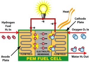
Fuel cells are similar to batteries in storing energy, but they do not need to be recharged, unlike batteries. As long as fuel is available, these devices can generate power and heat. You have two electrodes with a fuel cell; one is negative, the other is positive, an electrolyte surrounds both. The anode receives a fuel source like hydrogen when using a fuel cell, while the cathode gets air. A catalyst at the anode of a hydrogen fuel cell divides hydrogen molecules into protons and electrons opposite the cathode.
Electricity generates when electrons go across a circuit and back again. The protons go through the electrolyte to the cathode, where they combine with Oxygen and electrons to create water and heat.
Fuel Cell: Structure & Components
Current research on fuel cell vehicles is centered on polymer electrolyte membrane (PEM) cells. PEM fuel cells are constructed from a variety of materials layered on top of one another. A PEM fuel cell consists of the following components.
The MEA, which contains the membrane, catalyst, and gas diffusion layers, is the heart of a PEM fuel cell (GDLs). Gaskets create a protective layer around MEA to thwart gas leakage, while bipolar plates are used to join separate PEM fuel cells into a fuel cell stack and provide pathways for gaseous fuel and air.
Membrane-Electrode Assembly
Polymer Electrolyte Membrane
The polymer electrolyte cell wall, or PEM (also known as a proton exchange membrane), is a precisely engineered material that resembles regular plastic wrap for the kitchen and only conducts positively charged ions while blocking electrons. The PEM is critical to the fuel cell’s operation because it controls which ions may flow between the anode and the cathode. The chemical process would be disrupted if any other chemicals passed through the electrolyte. The layer used in transportation applications is fragile—as thin as 20 microns in certain situations.
Catalyst Layers
The anode layer and the cathode layer both have catalyst layers added to them. Catalyst layers commonly use nanometer-sized platinum particles distributed on a carbon substrate with a large surface area. The supported platinum catalyst is combined with an ion-conducting polymer (ionomer) and placed between the membrane and the GDLs. Hydrogen molecules are divided into protons and electrons using a platinum catalyst on the anode. The platinum catalyst on the cathode reduces Oxygen by interacting with protons produced by the anode, resulting in water. The protons may go through the catalytic layers because of the ionomer incorporated in there.
Gas Diffusion Layers
By allowing substances and product water to move more easily between catalyst layers, GDLs help reduces reaction time. Each GDL is made out of a thin layer of carbon paper with polytetrafluoroethylene partly coating the carbon fibers (PTFE). The GDL’s pores allow gases to diffuse quickly. The hydrophobic PTFE avoids excessive water accumulation by keeping these holes open. The microporous layer, a thin layer of high-surface-area carbon combined with PTFE, is commonly used to cover the inner surface of the GDL.
Hardware
Some hardware components are also essential to get the system going.
Bipolar Plates
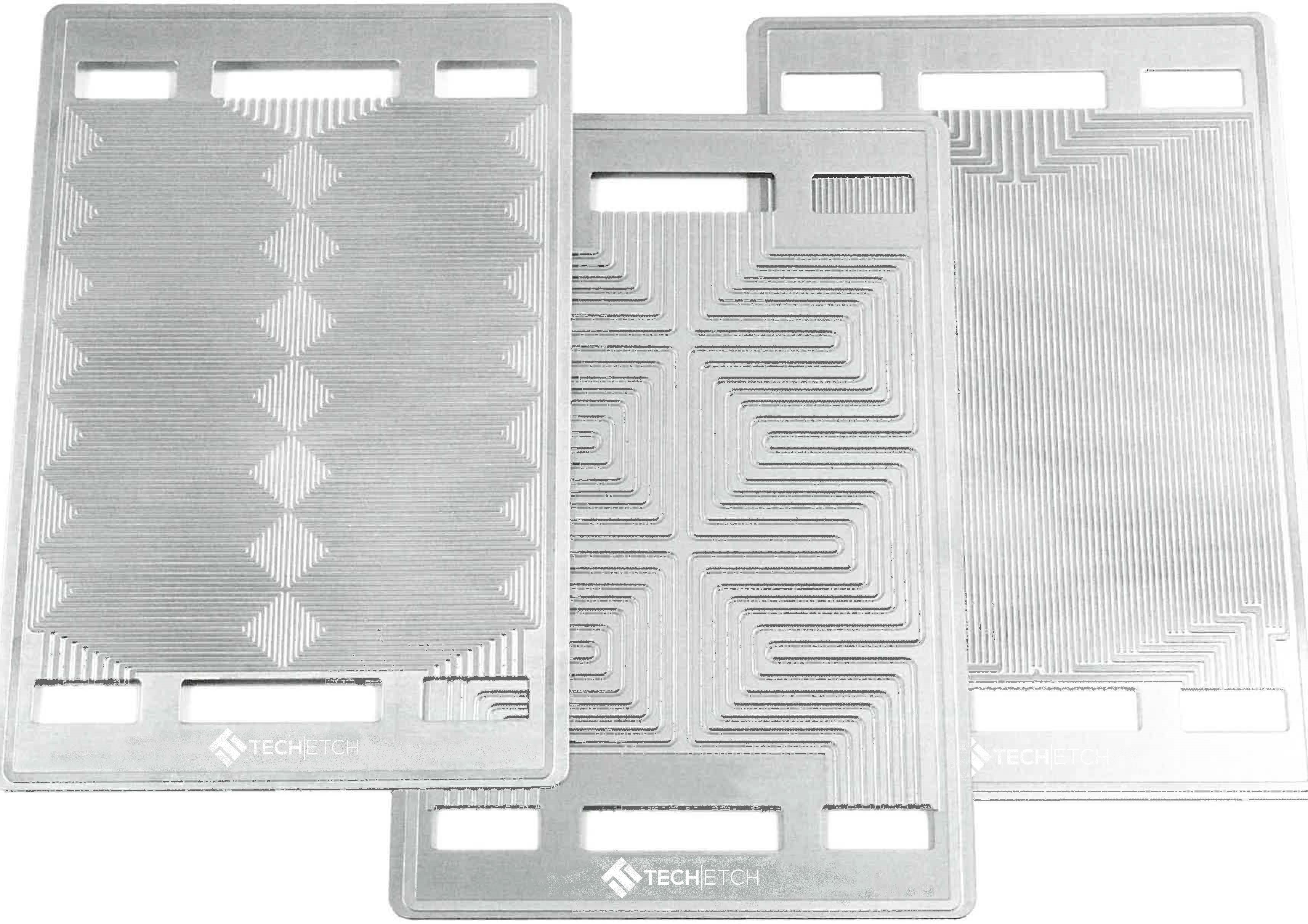
Under standard operating settings, each MEA generates less than 1 V, although greater voltages are necessary for most applications. As a result, several MEAs are often linked in series by stacking them on top to provide an output voltage that may be used. Each cell in the stack is separated from its neighbors by two bipolar plates. Plates made of metal, carbon, or composites transmit electricity between cells while also strengthening the heap as a whole. Leaves usually have a “flow field,” a series of channels milled or stamped into the plate to permit gases to pass over the MEA.
Gaskets
There are two bipolar plates in a fuel cell stack for each MEA. However, gaskets are needed to seal the MEA’s edges to prevent leakage. Spongy polymer is commonly used to make these gaskets.
Reasons Why It’s A Promising Sector
There are several uses for fuel cells, including automobiles, manufacturing constructions, and grid-scale long-term energy systems in reversible systems. Fuel cells may also be utilized for a wide range of other purposes. There are numerous advantages to using fuel cells over traditional combustion-based systems in many power stations and automobiles. Fuel cells are also more efficient than gasoline engines at converting chemical energy from fuel directly into electrical energy and may do so at efficiency surpassing 60%.
Contrary to gasoline engines, fuel cells emit a fraction of the pollution. Only water is emitted by hydrogen fuel cells, which solves critical climate change issues since they produce no carbon dioxide. Additionally, there are no particulate emissions that contribute to smog or pose a health risk at the site of operation. Because they have very few movable parts, fuel cells operate quietly.
Current Market & Future
In 2012, fuel cell sector earnings topped $1 billion worldwide, with Asia-Pacific nations exporting more than three-quarters of the world’s fuel cell systems. However, as of January 2014, no publicly traded firm in the industry has turned a profit. In 2010, the total number of fuel cell stacks transported worldwide was 140,000, up from 11,000 in 2007. And from 2011 to 2012, the worldwide shipment of fuel cells increased by 85% annually. Tanaka Kikinzoku increased the size of its production facilities in 2011.
Nearly half of fuel cell exports in 2010 were stationary, rising from almost a third in 2009, as well as the four major fuel cell producers were the United States, Germany, Japan, and South Korea, the Fuel Cell Industry said in 2010. As of January 2011, the Department of Energy’s Solid State Energy Conversion Alliance estimated that the cost per kilo-watt installed for stationary fuel cells ranged from $724 to $775. Bloom Energy, a prominent fuel cell provider, said in 2011 that its fuel cells provided electricity at the cost of 9–11 cents per kilowatt-hour, including fuel, maintenance, and hardware.
Conclusion
Until we can completely shift our dependencies to renewable energy, we can’t really stop extracting and consuming fossil fuel. But what we can do is be a bit more sensible about how we use it. Fuel Cells give us a chance to prolong our limited reserve of natural energy sources and reduce the adverse effects on the environment. So it’s high time to switch to a more sensible method and take the necessary steps to prevent the inevitable.

