At Tech Etch, we use a photo-etching process to manufacture light-gauge metal parts. This process allows us to create metal components with exacting tolerances that cannot be created through another process.
All configurations, tolerances, and dimensions are functions of the metal thickness. The guide on this page goes over the practical limitations of the photo-etching process. Here, you’ll learn the limitations and requirements for slots, spaces, holes, and construction dimensions of your metal parts.
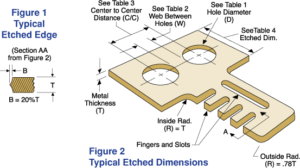
In certain cases, these limitations can be exceeded but with a reduction in yield percentage. The Figures to the left offers a visual representation of these features. Speak with our team for design assistance when you need to go beyond these limitations.
Dimensions
Holes and slots
Generally, the width of a slot or the diameter of a hole can’t be smaller than the thickness of the metal part. This measure can change as the metal becomes thicker. A more exact relationship is illustrated in Table 1.
Inside corner radius
The smallest inside corner radius is proportional to the thickness of the material. Talk to our factory if smaller or sharper radii are required.
Table 1: Holes or Slot
| Metal Thickness (T) | Diameter or Width |
|---|---|
| .001″-.005″ | 1.1 Times Metal Thickness (Min. .003″) |
| .005″ or Over | Min. of 1.1 Times Metal Thickness |
Fingers and webs
Typically in the photo-etching process, the finger or web width needs to be at least the same size as the material thickness. As the material thickness changes, this measure also changes. A more exact relationship is illustrated in Table 2.
Outside corner radius
The outside corner radius must be at least 75 percent of the material’s thickness.
Table 2: Web or Finger
| Spaces Between Holes (W) | At Least Metal Thickness |
|---|
Tolerances
Center to center
For the photo-etching process, the stability of the photo tooling material is the basis for the tolerances of the material. Consult our team for more information on alternate tooling materials. Table 3 illustrates the practical tolerances attainable from industry standard Mylar tooling.
Photo-etched dimensions
It’s practical to have a tolerance of ± 15 percent of the material thickness. A more exact relationship is illustrated in Table 4.
Table 3: Center to Center Tolerances
| C/C Dimensions (inches) | Tolerance Attainable |
|---|---|
| 1.0″ or Less | ±.0005″ |
| 1.0″ – 3.0″ | ±.0010″ |
| 3.0″ – 6.0″ | ±.0020″ |
| 6.0″ – 10.0″ | ±.0030″ |
Table 4: Etched Dimension Tolerances
| .001″ | .002″ | .005″ | .010″ | .015″ | .020″ | .040″ |
|---|---|---|---|---|---|---|
| Empirical | ±.0010″ | ±.0010″ | ±.0015″ | ±.0020″ | ±.0030″ | ±.0050″ |
Thickness (T) (inches)
